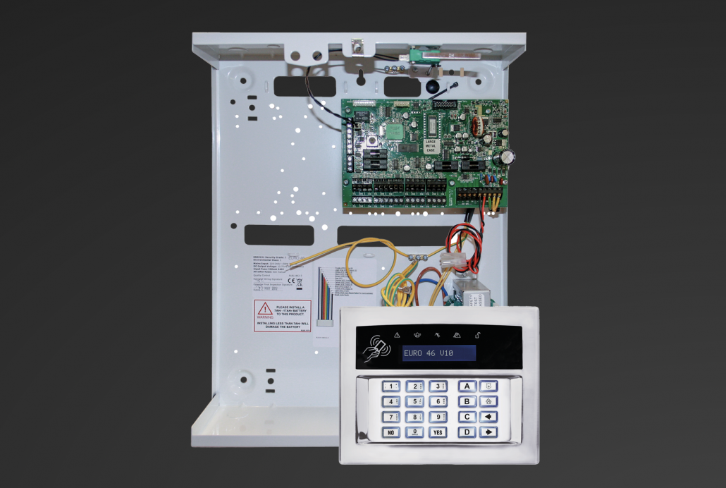
Pyronix Wireless Intruder based on Euro46 V10
Pyronix EURO46 Wireless Setup
with EURO Zem32-WE, wireless Door contacts and wireless PIR
Recently we have installed Pyronix Wireless Intruder Alarm and it included:
1x panel EURO 46 V10
1x keypad EUR064CL
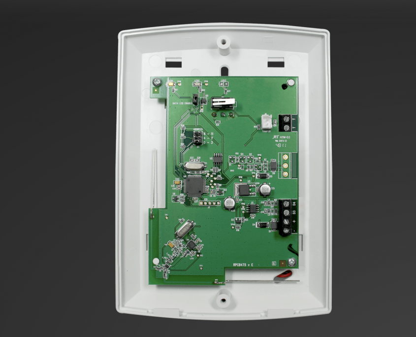
1x wireless module EURO-ZEM-32-WE
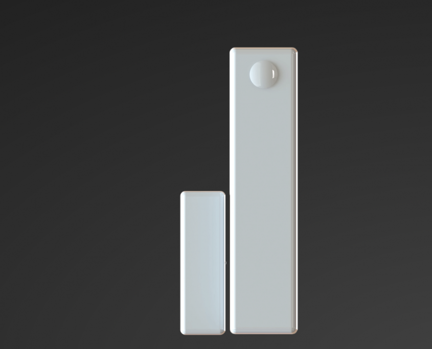
2x two-way sensor MC1MINI-WE
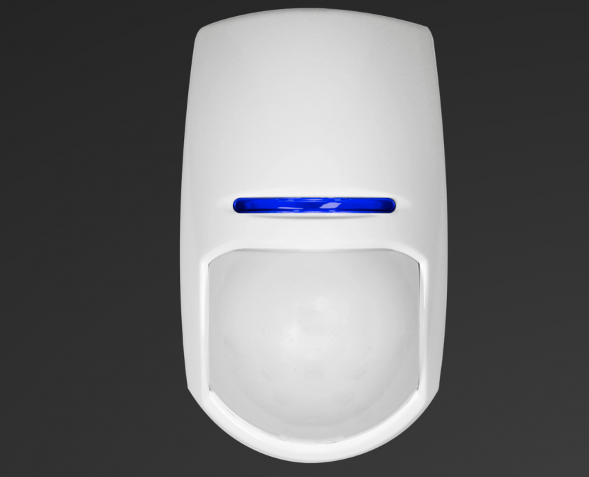
2x two-way internal motion detector KX10DP-WE (PIR detector).
In this article, we will have a look at Pyronix EURO46 Wireless Setup. Ideal configuration for homes or offices that require smart Intruder Alarm Solution.
Hint: If your install is based on Pyronix wireless devices, we suggest to set up all wireless devices on your desk prior to the installation to final location. Pyronix EURO46 Wireless Setup
Step 1 - Wiring up
- Connect power to the Pyronix Euro 46 V10 panel as per your Pyronix installation manual but do not power it up yet.
- However, if you are using “wired” keypad rather then wireless keypad, please refer to manual that came with your Keypad
- Wire up the wireless module EURO-ZEM-32-WE. This is additional module and needs to be purchased separately. Please refer to manual of EURO-ZEM-32-WE for correct wiring.
Step 2 - Remember your Codes
In the first place, please make sure you know what is your default Master and Engineers code. As a matter of fact you will need this information later on. Our default codes are as follow:
- Master: D2222
- Engineer: 1111
Step 3 - Power up and Set Time & Date
- After all, you are now ready to power up EURO 46 V10 panel. This should power up your Keypad and EURO-ZEM-32 WE if installed correctly.
- To begin with, enter your Engineers code (1111 by default) and start programming.
- First, set up “TIME&DATE and YEAR”
Step 4 - Install Zems to achieve Pyronix Wireless Intruder
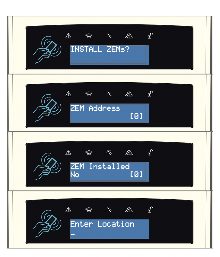
- Now that we want to have Wireless Pyronix Intruder, the next step is to install ZEMS – wireless unit. Next browse through the main menu and stop until you get to “INSTALL ZEMS?” Here is where you will be setting up your wireless module. This will allow you to connect all the wireless units, such as PIR or door contacts.
- We are using only 1x ZEM and we will set our Address on [0], click YES. Now you should see your ZEM Installed as ZEM32WE.
- “Enter Location” – you name it as you’d like it. Once you through these steps, your wireless unit is ready and you can start to program wireless devices.
Hint: Afterwards, exit engineer mode so the ZEM can be saved and recognised by the system before wireless devices can be added.
Step 5 - Learn Devices - Inputs
Wireless devices are very easy to Program. First you have to open up your wireless device and remove the little bit of paper to make battery alive. Then go back to your keypad and continue there.
- In the main menu, go to WIRELESS DEVICE CONTROL —> Control Inputs —> Learn Devices —> Input …. You have to choose one that is available. As we have addressed our ZEM as 0, our next available wireless Input is INPUT 9.
How to LEARNT wireless INPUTS:
- Next, press the learn button on your device and hold it for about 5 seconds. The LEDs cycling through. Once it is learned, you will get audio confirmation and you will be able to see it under the Input option as LEARNT. For detailed wireless pairing refer to your device manual that comes with it.
- Please proceed with all other wireless devices and lear them in the same way.
Step 6 - Change Inputs
After you have learnt all of your devices, go back to the main menu and browse to “CHANGE INPUTS?” Select your “Learned input” —> YES, in Input Type navigate through by using the arrow signs. Select your desired input. You will find several types you can use and the most used ones are:
Most used Input types:
- Intruder – Set the alarm on the activation. Usually your back door DC or PIR that are not in your way to trigger the alarm before you get to the Keypad to “set or “unset” the alarm.
- Final exit – This Input type is used for your final device, ex your Front door.
- Entry Route – this Input is on your Entry route to set or unset the alarm, after you enter the premises through “Final Exit” input.
- HU – Hold Up is your Input that is often your for Panic buttons on Receptions. Next select Input Area [A, B, C or D] , go through the rest of the menu, where you will enter name, description and location. Please refer to your install manual if you wish to change them.
Step 7 - Mode, Timers, Volume Control & System Options
- CHOOSE MODE? – To demonstrate, we have used 1k/1k. However, if you are using wired devices (Door contacts or PIR’s) please refer to your install manual for that particular device and set your mode correctly.
- CHANGE TIMERS – When you want to set your time for Entry or Exit, using Keypad or App and for different Areas (A / B / C / D )
- VOLUME CONTROL – Next step can help you find different volume levels for different task. Please adjust to your liking.
- SYSTEM OPTIONS – Plenty of options here so have a browse through and refer your programming guide to explore all options. However, most important set up here is “Exit Modes”. Here you have to tell the system how would you like to SET or UNSET your system. For demonstration purposes we have selected for our area A – EXIT MODE – TIMED.
Step 8 - Engineers Test
ENGINEERS TEST:
- After all, it is advisable to proceed with few Engineers test. First test you should proceed with is Walk. This will let you know if your devices are working correctly. “Walk test” —> YES. Now select areas you would like to test (we are testing) —> A. To begin with, walk the premises and make sure you are being seen by PIRs and Door contacts that you have installed.
TEST SIREN:
- Second, “Test Siren”. This will give you and idea if you Bell has been wired correctly (Please refer to manual for correct wiring). When you are ready, “Test Siren” —> YES and you should hear your Siren/Bell. As mention earlier on, here you can find many helpful test that you should use to make sure you have completed you install correctly. Please refer to your programming manual for further instructions.,
Step 9 - Diagnostics & Communications
Diagnostics and Communications are great tools. Use them to check if your Intruder is doing what is suppose to do.
- DIAGNOSTICS – From battery status, signal strength, Communications issues etc etc.
- COMMUNICATIONS – If you would like to use APP to set or unset, you are in the right place. Select YES —> your app —> YES. Now system will generate System ID, please make a note as this will be required later on to add your cloud account. —> Cloud Password – type your password and again, make note as you will need to use that later to set up yours system on the cloud. —> Security level – Normal (0) —> YES —> App password – make note as you will need to use that later to set up you app on the phone —> Always Poll Cloud —> YES. Now you have completed setting up your up in the panel.
Step 10 - Pyronix Cloud.
PYRONIX CLOUD – Log into your Pyronix Cloud account and follow instructions online.
https://www.pyronixcloud.com
Pyronix EURO46 Wireless Setup
We hope you find this article helpful. If there is element that doesn’t exactly meets your setup, get in touch with us by calling 0203 653 1380 or via our web form.

